
Major Works
The John Hancock Center
Chicago, Illinois, 1969, 1127ft, Steel
New Heights for Chicago
 |
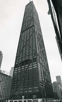
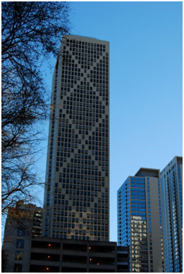
| Fig. 1: The John Hancock Center (Photo by J. Wayman Williams Jr.) |
The John Hancock Center (Figure 1) was completed in 1968 by Skidmore, Owings, and Merrill (SOM) at 876 North Michigan Avenue in Chicago, Illinois. The 100-story, 1,127 foot tall structure was the tallest building in the world outside of New York City at the time of completion, and heralded Chicago’s arrival on the global stage in the race for tall building. For the Hancock’s chief engineer, Fazlur Khan, the feat symbolized a more personal accomplishment –it served as validation of his belief that constructing tall buildings at unprecedented scales required designing innovative structural systems. The Hancock Center debuted and expressed Khan’s “trussed tube” structural system making it a notable structural and social symbol, as well as an emblematic landmark for the city of Chicago.
In the 1920s, Chicago had seen a major expansion in industry, a high availability of jobs, and a subsequent increase in African American migration to the city from the South. But by the late 1950s, this development began to reverse. Chicago, along with the nation’s other large cities, was faced with the burgeoning phenomenon of ‘white flight’ – the flood of upper and middle-class citizens abandoning the inner city in favor of the surrounding suburbs.1 Over the decade, Chicago’s population shrank significantly. This sudden shift in the city’s demographics and declining population greatly affected the manufacturing industries resulting in increased unemployment and poverty.2 As the city faced decay, Mayor Richard Daley was elected in 1955. Along with Chicago’s City Council, he began to focus his attention on revitalizing the city of Chicago through redevelopment of downtown and areas surrounding the central business district. Developer Jerry Wolman recognized the opportunity and need for this tower as early as 1964. Recognizing that a planned public rapid-transit line that would pass by near the neighborhood of the site would create an opportunity for high-density residences and offices, he responded to this anticipated demand by acquiring the site on North Michigan Avenue. Though the transit line was never built, the demand for high-density development remained, due to beginning of gentrification and urban re-development, as well as the cachet brought about by media attention on the project itself.
 |
| Fig. 2: Fazlur Khan (left) and Bruce Graham (right) standing beside a model of the John Hancock Center |
Upon winning the bid for the site, Wolman approached SOM to design the building, considering them to be the best architectural engineering firm in the country. The firm assigned the project to a team of about 60 architects and engineers, led by architect Bruce Graham and engineer Fazlur Khan.3 (See Figure 2).Given the design constraint of providing 2.8 million gross square feet of floor-space, the design team initially proposed a multi-use design concept involving a 70 story office building and a separate 45 story residential building. When a social club occupying a portion of the property would not agree to sell its building, the design teams began to consider a single-tower scheme that incorporated both offices and residences. Initially, the analysis of engineers at SOM found that the structural demand required of such a tall building made it economically unfeasible using traditional structural solutions. For this building, a new structural system would be tried.4
Forces and Form
In multi story buildings, the controlling factor in design is usually the lateral load imposed by wind forces. Khan demonstrated that increases in the height of a building lead to a corresponding increase in structural material required to account for the effect of lateral load. Khan called the difference between the amount of material needed for considering lateral loads to that required for only gravity loads a building’s “structural height premium.”5 (See Figure 3) Khan recognized that because the structural height premium was different for different building heights, each range of heights called for a different type of structural system.6 Khan recognized that avoiding this height premium for a building as tall as the Hancock required a structural system that exhibited tube-like behavior, giving it better wind resistance. For structures above 60 stories, a rigid-box type structural system, with all exterior wall elements acting together like the sides of a tube, was the most fitting solution. Khan had already partially achieved this tube-like behavior in the concrete Chestnut-Dewitt Apartment Building with a framed tube structural system, which involved closely spaced exterior columns and stiff spandrels. Essentially, the framed tube could be understood as a perforated tube, which behaved when submitted to lateral loads partially like a tube and partially like a rigid frame.
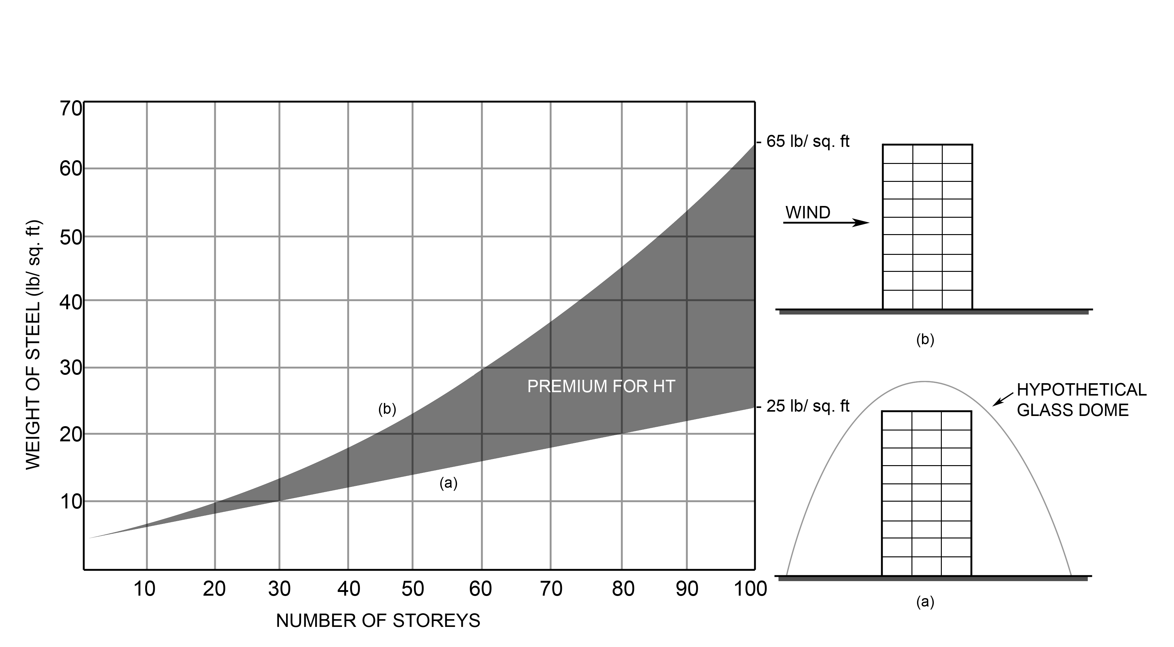 |
| Fig. 3: Structural Height Premium for structural steel buildings. The lower curve represents theoretical designs for gravity loads exclusively; the upper curve incorporates additional structural material required for resisting lateral wind and seismic loading (diagram adapted from diagram of Yasmin Khan, ‘Engineering Architecture: the vision of Fazlur R. Khan’) |
SOM’s initial calculations for a single mixed-use tower at the Hancock site demonstrated that, for the total square footage desired, a tower of the required height using the framed tube system would be costly and unfeasible due to the amount of structural steel that would be required in order to handle wind loading. At that moment Khan proposed using an untried structural system, in which the exterior columns were tied together by adding diagonals in the exterior wall planes. He called this system the trussed (or braced) tube. Though the trussed tube had not yet been implemented in a building when he proposed the system. Khan had already spent a considerable amount of time studying the way the system worked.
At the Illinois Institute of Technology Together, Khan and Goldsmith worked with a graduate master student named Mikio Sasaki on a proposal for a steel tall building thesis project. The work involved designing a tall building that employed a structural system with crossing diagonals spanning multiple stories.7 In the project, the diagonals were employed to brace the columns and spandrels against swaying. Khan recognized the potential in this “optimum column-diagonal-truss tube” structural system for not only lateral-bracing but also for distributing both gravity and wind loads to the corner vertical columns. The thesis indicated that multi-story diagonal bracing at approximately 45° would improve lateral stability for tall structures, like the Hancock, which are highly affected by wind loads.8 Khan confidently presented his research and design proposal to the design team. The new system proved to be economically viable and structurally sound, and Wolman approved the design.9
The trussed tube achieves purer cantilever behavior than a tube without the diagonals (framed tube). According to Khan’s analysis, in the framed tube, only 30% of the total horizontal deflection is due to cantilever action, while 70% is due to the frame action.10 Where the framed tube suffered from shear lag due to the flexibility of spandrel beams, the behavior of the X-braced Hancock was “very similar to that expected in a true cantilever tube.”11 Without bracing, wind and gravity loads are largely handled separately, whereas the redistribution of the stresses through the diagonal bracing allows the trussed tube system to handle loads in a more integral manner – the tube becomes a stiffened box.
In the framed tube system, gravity loads travel vertically straight down from the top to the bottom through the columns of the framed walls of a tall building. The trussed tube, however, allows for a more even redistribution of gravity loads in the system through the diagonal bracing. In Khan’s own analysis, he showed that the Hancock’s braced system allowed vertical loads to be distributed evenly to the columns. Figure 4 demonstrates this effect where two 70-kip point loads are applied symmetrically to the top of the tall building (this type of loading is not a realistic scenario, this is just for demonstration). As the forces descend, the cross bracing spreads the loads between the columns, until each of the 7 columns carries 20 kips at the base. As seen in the diagram and the graph of axial column forces, each time a vertical column intersects the diagonal bracing, some of the load is transferred either to or from the bracing. Over the entire height, the forces in each vertical column converge until they are equal.
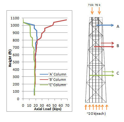 |
| Fig.4: Qualitative diagram demonstrating the redistribution of vertical loads in the trussed tube system of the Hancock. The graph (left) visually demonstrates the gradual convergence of the loading from the top to the columns at the bottom; the tall building diagram (right) shows how the magnitude (signified by line thickness) of the axial loads in the members diminishes as the loads travel down the tower. |
The success of the Hancock Center’s design paved the way for trussed tube construction in future buildings. After completing the design for the Hancock, Khan transformed the concept to concrete construction, replacing the diagonal members intersecting window openings with filled-in window panels, combining aspects of the framed tube and trussed tube structural systems. This innovative solution was applied in Chicago’s Onterie Center (Figure 5) and 780 3rd Avenue in New York City (Figure 6).
The Caisson Calamity
 |
| Fig. 5: Onterie Center, in Chicago using the trussed tube structural system in concrete |
The construction of the Hancock Center proved to be a challenge befitting the creation of a groundbreaking structure. The most significant issue came from the geology of the site, which contained bedrock buried far deeper than anticipated. For a building of excessive size and mass, it is commonplace to support the high vertical load using caissons– deep concrete columns anchored to bedrock. In the case of the Hancock Center, 57 concrete caissons needed to be anchored to bedrock that reached up to 197-feet below grade – the deepest foundation ever built at the time.12 The caisson construction process employed a massive auger drill, which bore a hole in the soil until the bedrock was reached. A steel sheath was lowered into place and filled with concrete, which dried to form the caisson. Since the sheaths were costly and were not long enough to cover the entire length of the caisson, the caissons were poured in segments, allowing the sheaths to be reused. A sheath was lowered, the concrete would be poured, then the sheath was raised until it was almost out of the poured concrete, then the next layer of concrete was poured. This process was repeated until the caisson reached ground level and the sheath could be removed.13
 |
| Fig. 6: The slender 780 3rd Avenue, in NYC, clad in rose granite uses the trussed tube structural system in concrete. |
In the summer of 1966, after this process had been completed on all 57 caissons, one six-foot diameter caisson suddenly shifted downwards approximately an inch in under 24 hours under the self weight of only one steel column. There was no obvious explanation as to why this would occur. In spite of the costs of halting the project, Khan determined that construction should be halted until the cause could be determined. Checking the caisson required a cutting-edge examination. Three holes were drilled into the caisson from top to bottom, into which sensors were gradually lowered. As the sensors were lowered, the sensors would emit and capture pulses. By analyzing the wavelengths of the captured pulses, the composition of the caisson could be mapped over the entire length of the caisson. The test showed that Khan’s safety-first intuition had been correct. The caisson had a 14-foot long void filled with loose earth and no concrete, which had been created by the sheath pulling up concrete as it was being raised. The test was repeated for every single caisson, and 26 of the 57 were judged to be defective.The repair process, supervised by Khan, took 4 months of nonstop work and 11 million dollars in repairs. Overall, the massive delay in the project caused extensive financial difficulties for Jerry Wolman, who ended up fronting the full cost of the repair and eventually sold the building to John Hancock Mutual Life in December, 1966.14
Conclusion
Though Khan was intimately involved in the design process, in its final form, the John Hancock Center reflects his collaborative work with architect Bruce Graham. The design process involved a creative exchange and mutual consultation between the two. Because the design for the Hancock arose both out of structural and architectural sensibilities, the built form can be seen at once as an innovative structure and a bold architectural design.
Khan’s technical expertise in structural engineering gave him the knowledge to investigate new structural systems with great visual impact.15 Khan was devoted to the idea that “a building’s natural strength should be expressed,”16 and this devotion to the unity of the building’s aesthetic and structural form is characteristic of all his designs. Rather than simply serving as visual metaphors for internal structural realities, the Hancock’s external members express the manner in which the structural system works. It was by pushing the structure to the outside through his trussed tube that Khan found a creative way to allow the structural reality to express itself visually.
Initial reception of the John Hancock Center by critics was mixed. While some praised the Center for its strong, bold aesthetic, others were less enthusiastic. One critic called it “an ugly, steel-braced colossus.”17 Others thought that the dark, modernistic tower was an eyesore that did not fit into the context of the surrounding cityscape. As the city has grown, however, more modern skyscrapers, including Khan’s Willis Tower (formerly called the Sears Tower), have joined the Hancock in populating the Chicago skyline. And, though the Hancock’s bold diagonals feature strongly and cause the tower to stand out from a close vantage point, they become less distinguishable relative to the scale of the building as a whole. From a distance, the Hancock remains recognizable for its tapering form and soaring antennae, serving as a familiar landmark in Chicago’s urban landscape.Over the years, the Hancock Center has come to be held in high esteem by both Chicago residents and the international community alike. Luxury residences and office spaces in the tower continue to hold cachet for tenants, and the building has been lauded as an architectural icon in relatively recent years, gaining recognition through winning the Distinguished Architects Twenty-five Year Award from the American Institute of Architects in 1999 and being included in the World Federation of Great Towers.
1. Martin, Elizabeth Anne. Detroit and the Great Migration, 1916-1929. Ann Arbor: Bentley Historical Library, University of Michigan, 1993.
2. Gentrification in West Town: contested ground.. Chicago: Nathalie P. Voorhees Center, 2001.
3. Modern Marvels: John Hancock Center. DVD. Directed by Emily Lau. New York: History Channel/New Video, 2008.
4. ibid.
5. Khan, Fazlur R. "Report on Column-Free Multi-Story Buildings With and Without Rigid Cores." SOM (1988): 1-18.
6. ACI Committee 442."Response of Buildings to Lateral Forces."ACI Journal 68, no. 2 (1971): 81-106.
7. Khan, Yasmin Sabina.Engineering architecture: the vision of Fazlur R. Khan. New York: W.W. Norton, 2004.
8. Khan, Fazlur R. "New Structural Systems for Tall Buildings and Their Scale Effects on Cities."Vanderbilt Symposium on Tall Buildings 1, no. 1 (1974): 114-115.
9. Modern Marvels, (2008).
10. Tucker, JB. "Superskyscrapers: Aiming for 200 stories." High Technology 5, no. 1 (1985): 50-63.
11. Khan, F. (1972).Structural Systems for Multi-Storey Steel Buildings.Research Paper, pp 26-35
12. Rernsberg, Charles. "100 Floors of Modern Living."Popular Mechanics, June 1968. "The John Hancock Center."SOM. http://www.som.com/content.cfm/john_hancock_center (accessed December 1, 2010).
13. Modern Marvels, (2008).
14. Ibid.
15. Billington, David P. The tower and the bridge: the new art of structural engineering. New York: Basic Books, 1983.
16. Ibid.
17. Modern Marvels, (2008).