Major Works
Brunswick Building
Chicago Illinois, 1965, 474ft, Reinforced Concrete
Introduction
 |
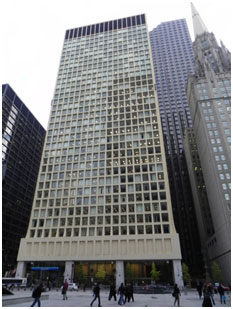
| Fig. 1: Brunswick Building: loads in the closely spaced perimeter columns are transferred through the transfer beam to the widely spaced columns at ground level |
The Brunswick Building (Figure 1) was commissioned in 19611 and completed in 19652, and became the tallest reinforced concrete structure of its time. At the time it was being built, Chicago was undergoing rapid inner-city development, fuelled by the urgent need for more office space. This was an after-effect of the Depression, which had seen a halt in new developments between 1945 and 1955 within downtown Chicago, also known as the Loop. Things were made worse by a height restriction imposed on new developments in the 1940s.3 1955 saw the election of a new mayor, Richard J. Daley, who realized the need to revitalize the inner-city, and commissioned a development plan that included providing support and financial incentive for construction planning4. Over 1 million square feet of office space was added in downtown Chicago in 1958.5
The 1960’s was also a time of growing consciousness of the value of open, street-level plazas, and integration of high rises with the street level and surroundings. With this in mind, it was of great importance to develop structural systems that could allow for taller building construction. If buildings were made taller, then the same floor area could be created on a smaller footprint, and thus allow for these plazas to be built. The purpose of these open spaces was to allow relief for the pedestrian from the narrow “canyons” created by the tall buildings. For the Brunswick Building, chief design architect Bruce Graham and senior designer Myron Goldsmith hoped to open up a 51-foot-wide plaza containing reflecting pools, trees, and public art, but none of this was realized as the orientation prevented sunlight from entering the space. Twenty years later, a sculpture by Picasso was placed in the plaza between the Brunswick Building and the Daley Civic Center.
Forces and Form
The structural system of Brunswick Building consists of a concrete shear wall core surrounded by an outer concrete frame of columns and spandrels.6 At first, Khan did not consider that the outer frame would contribute significantly to the lateral stiffness of the building needed to take wind loads. But as he investigated the structural framework in more detail, he started to suspect that the close spacing of the columns could influence the building’s structural behavior. Together with other engineers, he carried out a careful approximate analysis of the two structural systems at play: (1) the shear wall core, and (2) the outer frame with a column spacing of 9’4”. They discovered that subjected to lateral wind loading the frame combined with the shear wall core gives the structure a greater stiffness than previously than just one system (shear wall or rigid frame) acting alone.
 |
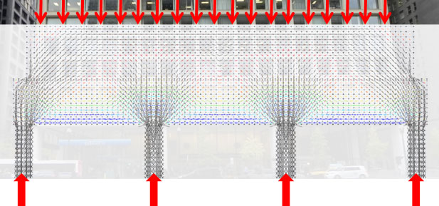
| Fig. 2: This elevation of the lower part of the Brunswick structure shows the transfer of loads from closely spaced columns above to widely spaced columns below through a transfer wall beam |
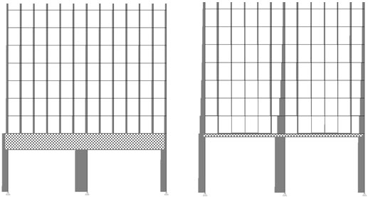
One of the main features of the Brunswick Building is the 24 ft deep transfer wall beam near the ground level. Figure 2, shows how the transfer wall beam directs gravity loads from the closely spaced columns above to widely spaced columns at the ground. To study the effect of the depth of this transfer wall beam, we performed two analyses for a 2 bay equivalent system: one using the actual transfer wall beam dimensions, and another with the depth of the transfer beam as one tenth of the actual beam depth. Representations of the axial forces through the members are shown in elevation in Figures 3(a) and (b).
 |
| Fig. 3 a & b: Axial forces in the perimeter columns with (a) a full size transfer (24.1 ft depth), and (b) a beam with a depth 1/10 of the full size beam (2.41 ft depth) |
In the full size 24 ft beam analysis (Fig. 3(a)) the total gravity force is divided almost equally among the thirteencolumns above the transfer beam (all axial forces in the columns have the same magnitude expressed in the diagram by identical line thicknesses). Below the beam, the force is then divided among the three base columns, with the central column carrying more of the load than the two outer columns. This is not the case for the one tenth depth transfer beam. Fig. 3(b) shows the distribution of forces above the girder as having more force carried by the columns closest to the base columns and less force carried by the columns in the center of the spans between the base columns. The columns directly above the base columns see a gradual increase in axial force as they near the transfer beam (shown in figure 3b by increasing line thicknesses), while the other columns see a decrease in axial force. An “arch-like” effect appears as the forces gradually move towards the stiff column supports at the base. This shows that the depth of the transfer beam has a significant effect on the way in which the forces in the closely spaced columns above the wall beam distribute to the widely spaced columns below.
Before beginning construction, Khan made sure that all possible loading conditions on the tall building were evaluated and produced a number of charts that predicted its behavior, all made possible through physical experimentation coupled with creative analytical thinking. For example, Khan worked with several professors on the transfer wall beam testing at the Structural Research Laboratory at the University of Illinois preceding construction. Some concerns had been raised regarding heat of hydration, an unusually small span-depth ratio, and nonconventional deep beam construction.”7 These tests ensured the feasibility of the beam which was at the time the “world’s largest concrete girder;”8 as a result, concerns were mitigated, as lab tests revealed a safety factor of 3.0, yielding in flexure, minimal effect on horizontal construction joints, and appropriate reinforcement was made with confirmation.9
Conclusion
 |
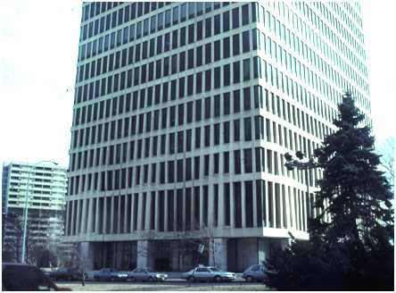
| Fig. 4: Marine Midland Bank in Rochester, NY with its structural undulating facade (photo by J. Wayman Williams Jr.)) |
The Brunswick Building represents one of the first uses of reinforced concrete in modern tall buildings. The lack of an external glass curtain wall accentuates the building’s beam-column framework by exposing the building’s bare concrete façade. The massive transfer wall beam transfers the forces from the closely spaced columns above to the widely spaced columns below. In future designs such as Two Shell Plaza and Marine Midland Bank (Figure 4), Khan makes this transfer of forces in a more fluent, gradual way.
The Brunswick Building marks the beginning of a series of Khan’s reinforced concrete structures.10 Over the 45 years that the building has been in existence, the Brunswick Building has stood the test of time. This was the first project for which Fazlur Khan was the project manager. His meticulous attention to detail and exploration of engineering innovations were just beginning and a sign of more to come.
1. Khan, Yasmin Sabina. Engineering Architecture: The Vision of Fazlur R. Khan. New York : W. W. Norton & Company, 2004.
2. SOM.Brunswick Building.[Online] http://www.som.com/content.cfm/brunswick_building. Accessed: 08.09.2011
3. Khan, Yasmin Sabina.
4. Ibid.
5. Pacyga, Dominic A. Chicago: A Biography. Chicago : The University of Chicago Press, 2009.
6. Khan, Fazlur R. The Bearing Wall.Architectural & Engineering News.
7. Khan, Yasmin Sabina.
8. Khan, Fazlur.“Current Trends.”1967, 578.
9. Khan, Yasmin Sabina.
10. Ibid.
